

Views: 0 Author: Site Editor Publish Time: 2026-09-14 Origin: Site


Modern process control, commercial HVAC systems, and industrial fluid management share a fundamental operational reality: they require exact parameter regulation. Maintaining precise space temperatures, balancing chemical mixtures, and controlling steam pressure cannot be achieved through simple binary isolation. Systems demand continuous, dynamic adjustments to match varying load conditions.
Relying on poor flow control mechanisms introduces severe systemic costs. Energy is wasted when systems overcompensate for inaccurate flow. Equipment suffers accelerated wear, particularly through pump deadheading when flow is restricted incorrectly. Process instability leads to off-spec products and compromised safety. Using non-modulating valves for throttling applications specifically invites rapid mechanical degradation, as these components are not engineered to withstand the destructive forces of high-velocity partial flow.
Specifying the correct modulating valve requires aligning valve body mechanics, actuator technology, and control signal infrastructure with the specific physical properties of the system's media.
Proportional Control: A modulating valve adjusts flow anywhere between 0% and 100%, allowing for precise partial flow based on continuous analog or digital control signals, unlike standard on/off valves.
Component Synergy: Effective modulation requires the correct pairing of the valve body, actuator (pneumatic or electric), and a smart positioner to eliminate hysteresis.
Sizing is Critical: Selecting a valve based merely on pipe size leads to failure; accurate Flow Coefficient (Cv) calculation is mandatory to prevent cavitation, choked flow, and valve hunting.
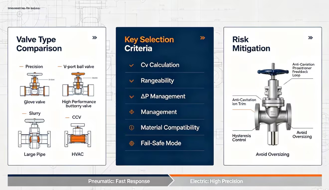
Application-Specific Geometry: Globe, V-port ball, and high-performance butterfly valves offer vastly different rangeability and pressure drop characteristics, dictating their suitability for steam, slurry, or chilled water.
Dynamic flow regulation forms the baseline requirement for modern fluid handling systems. Facilities must maintain specific system setpoints under constantly varying load conditions. A modulating control assembly achieves this by operating across part or all of its travel range, continuously adjusting the restriction in the piping network to match the real-time demands of the process loop. You cannot achieve this level of control with standard piping components.
The operational difference between binary states and continuous throttling dictates valve selection. On/off valves, commonly known as isolation valves, operate strictly in two positions: fully open to allow maximum flow or fully closed to stop flow completely. Gate valves and standard port ball valves fall into this category. Their internal geometry minimizes pressure drop when open and provides a tight seal when closed.
Proportional flow control requires a device capable of operating anywhere between 0% and 100% open. This continuous throttling allows for partial flow. Attempting to use a standard isolation valve for modulation introduces immediate mechanical failures. When you leave a standard gate or ball valve partially open, the fluid velocity across the narrow restriction increases dramatically. This high-velocity flow causes wire drawing—a severe physical erosion of the valve seat and trim. The fluid literally cuts channels into the metal. Furthermore, standard isolation valves exhibit non-linear flow characteristics. A 10% change in valve position does not equate to a predictable change in flow rate, making accurate control impossible for the system controller.
A functional modulating control loop relies on three distinct components working together. If one component fails or is specified incorrectly, the entire control loop becomes unstable.
Valve Body and Trim: This is the mechanical restriction element located inside the piping. The trim consists of the plug, disc, or ball, along with the seat. As the trim moves relative to the seat, it physically alters the flow area, changing the flow rate and pressure of the media passing through.
Actuator: The actuator provides the physical driving force required to move the trim against the pressure of the fluid. Actuators translate energy into mechanical motion and typically utilize electric motors, pneumatic diaphragms, or hydraulic pistons. They must generate enough thrust to overcome static friction and dynamic fluid forces.
Positioner: The positioner acts as the local brain of the assembly. It creates a feedback loop by comparing the incoming control signal from the central system to the actual physical position of the valve stem. If the valve is not exactly where the signal commands it to be, the positioner corrects the deviation by adjusting the air or power supplied to the actuator.
Selecting the correct mechanical restriction element requires understanding the engineering trade-offs of primary valve body designs. No single valve geometry works for every fluid application. You must match the internal mechanics to the physical realities of your piping system.
| Valve Type | Primary Motion | Best Field Applications | Engineering Trade-offs |
|---|---|---|---|
| Globe Valve | Linear | Steam headers, high-pressure gas, precise throttling | High pressure drop, large physical footprint, heavy |
| V-Port Ball Valve | Rotary | Slurries, paper pulp, viscous liquids | Lower precision at extreme low flow rates (under 10%) |
| High-Performance Butterfly | Rotary (Eccentric) | Large diameter piping, cooling towers, bulk water | Limited rangeability, cavitation risk at low opening angles |
| Characterized Control Valve (CCV) | Rotary | Commercial HVAC, chilled water loops, air handling units | Limited to lower pressure and temperature applications |
Globe valves utilize linear motion mechanics, where a plug descends into a stationary ring seat. This design forces the fluid to change direction multiple times as it passes through the valve body. This tortuous path results in excellent throttling capabilities and highly predictable flow characteristics. The rugged nature of the plug and seat makes them highly resistant to wear, even under high differential pressures.
Engineers specify globe valves primarily for steam regulation, high-pressure industrial processes, and precise gas flow control. They excel in applications requiring minute adjustments. However, the complex flow path creates a naturally high pressure drop across the valve, even when fully open. Globe valves also demand a larger physical footprint and require significant vertical clearance for the actuator assembly.
V-port ball valves modify the standard spherical ball by machining a characterized "V" notch into the ball or the seat. As the valve rotates open, the V-shape maintains a specific geometry that provides an equal percentage flow characteristic. Equal increments of valve travel produce equal percentage changes in the existing flow rate. This characteristic proves ideal for systems where pressure drop varies widely across the operating range.
The straight-through flow path and shearing action of the V-notch make these valves highly tolerant of debris. They represent the standard choice for slurries, viscous fluids, paper and pulp processing, and high-flow liquid applications. The primary trade-off involves control resolution. V-port valves struggle to maintain the same level of precision as globe valves at very low flow rates, typically becoming unstable when operating below 10% open.
Standard concentric butterfly valves perform poorly in throttling applications because the disc drags along the seat, causing rapid wear and erratic control. High-performance butterfly valves solve this by utilizing double or triple eccentric discs. The shaft is offset from the center of the disc and the centerline of the pipe. This geometry allows the disc to cam away from the seat immediately upon opening, reducing friction, minimizing wear, and providing a much more stable throttling profile.
These valves dominate large piping systems where installing a massive globe valve would be physically impossible. You will find them heavily utilized in commercial HVAC systems, cooling towers, chillers, and high-volume municipal water distribution. Users must account for their limited rangeability and the significant potential for cavitation if operated at very low opening angles under high differential pressure.
Characterized Control Valves (CCVs) were developed specifically to overcome the limitations of standard ball valves in commercial HVAC systems. A standard ball valve has a very rapid increase in flow during the first few degrees of opening, making precise temperature control nearly impossible. CCVs incorporate a specialized characterizing disc inside the valve inlet.
This disc restricts the flow area to mimic the highly desirable equal percentage flow characteristic of a globe valve, but within the compact body of a rotary ball valve. CCVs play a primary role in regulating chilled water, hot water, and air handling units to achieve highly accurate space temperature control within modern building management systems.
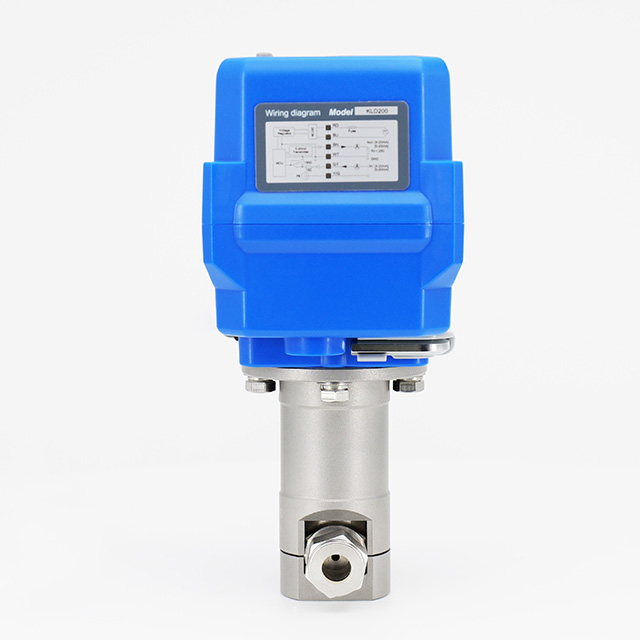
Determining how to power and control the modulating valve depends heavily on existing facility architecture, environmental conditions, and specific response time requirements. The mechanical valve body cannot function without appropriate actuation and a reliable communication protocol. You must match the actuator to the utilities available at the installation site.
Pneumatic actuators utilize compressed air acting on a diaphragm or piston to generate mechanical force. They remain the industry standard in heavy process environments due to their rapid response times and inherent fail-safe capabilities. By utilizing heavy internal springs, a pneumatic actuator can drive the valve to a safe position immediately upon loss of air pressure. They are also intrinsically safe, making them the default choice for hazardous or explosive environments. The obvious requirement is a reliable, clean, and dry compressed air infrastructure.
Electric actuators use motor-driven gear trains to position the valve. They offer exceptional precision and integrate seamlessly with modern Programmable Logic Controllers (PLC). Electric actuators require far less routine maintenance than pneumatic systems, as they eliminate the need for air compressors, filters, and tubing. The trade-offs include slower stroke times and more complex fail-safe mechanisms. Achieving a fail-safe state with an electric actuator typically requires internal capacitors or backup battery systems to drive the valve during a power outage.
The actuator and positioner require a control signal to determine the desired valve position. Analog signals remain highly prevalent across all industries.
4-20mA: The 4-20 milliamp signal is the heavy industry standard. It is highly immune to electrical noise and voltage drop over long cable runs. A reading of 4mA typically represents fully closed, 20mA represents fully open, and a drop to 0mA instantly indicates a broken wire or system fault.
0-10VDC: The 0-10 volt direct current signal is common in commercial HVAC environments. While effective for shorter distances, voltage signals are susceptible to electrical interference and voltage drop over long runs, which can lead to inaccurate valve positioning.
Digital and networked communication protocols are replacing analog signals in advanced facilities. Protocols like Modbus, BACnet, and Foundation Fieldbus allow two-way communication. The system not only sends a position command but also receives advanced diagnostics, actual position feedback, and predictive maintenance data directly from the smart positioner.
Selecting a modulating valve based on the existing pipe diameter guarantees poor performance. Proper specification requires rigorous engineering calculations to ensure the valve performs as intended without causing catastrophic system failure. A valve that is too large will control poorly, while a valve that is too small will restrict maximum system capacity.
The Flow Coefficient, or Cv, represents the universal standard for measuring valve capacity. Technically, Cv is defined as the volume of water at 60°F (in US gallons per minute) that will flow through a fully open valve with exactly a 1 psi pressure drop across it. It serves as the baseline metric for sizing.
Calculating the required Cv at minimum, normal, and maximum expected flow rates is non-negotiable. If a valve is sized only for the maximum flow, it will operate too close to the closed position during normal conditions, leading to instability. Rangeability defines the ratio of the maximum controllable flow to the minimum controllable flow. A valve with a rangeability of 50:1 can accurately control flow down to 2% of its maximum capacity. Matching the valve's rangeability to the system's expected flow variations ensures precise partial flow across all operating conditions.
Pressure drop and fluid velocity share a direct relationship. As fluid forces its way through the narrowed restriction of a partially open valve, its velocity increases significantly, causing a corresponding drop in localized pressure. If this pressure drop is not managed, destructive physical phenomena occur inside the piping.
In liquid applications, if the localized pressure drops below the fluid's vapor pressure, vapor bubbles form. As the fluid exits the restriction and pressure recovers, these bubbles violently implode. This is cavitation. The micro-jets generated by imploding bubbles tear away metal from the valve trim and pipe walls, sounding like gravel passing through the system. In gas and steam applications, excessive pressure drop leads to choked flow, where the gas reaches sonic velocity and flow rate cannot be increased regardless of downstream pressure. Engineers mitigate these destructive forces by specifying specialized anti-cavitation trims or multi-stage pressure reduction valve bodies.
The physical materials comprising the valve body and internal seals must withstand the media's temperature, corrosiveness, and pressure profile. Standard applications utilize carbon steel or cast iron bodies, while corrosive environments demand 316 Stainless Steel, duplex alloys, or specialized polymer linings. Soft seat materials like PTFE or PEEK provide excellent shut-off but have strict temperature limits. Metal seats utilizing Stellite overlays handle extreme temperatures and abrasive slurries but allow minor leakage.
Acceptable shut-off capabilities are defined by ANSI/FCI 70-2 seat leakage classifications. A modulating valve is primarily a throttling device, not an isolation valve. Class IV leakage is standard for metal-seated control valves, allowing 0.01% of rated valve capacity to leak when fully closed. Class VI requires a soft seat and represents bubble-tight shut-off. Specifying the correct leakage class prevents over-engineering.
Deploying control valves involves specific implementation risks. Recognizing the most common points of failure allows engineers to design them out of the system before installation. Field troubleshooting often reveals that mechanical failures stem from initial sizing errors rather than defective manufacturing.
Oversizing remains the most frequent error in valve specification. When a valve has a Cv much larger than the system requires, it must operate at a very small opening angle (often under 15%) to achieve normal flow rates. This leads to "hunting," a condition where the valve rapidly oscillates back and forth near the closed position as it struggles to find the correct setpoint. Hunting destroys control resolution, causes severe system pressure spikes, and results in premature wear of the valve seat and actuator linkage.
System safety during a power loss or control signal failure must be evaluated during the design phase. The actuator must drive the valve to a predetermined safe state to protect personnel and equipment.
Fail-Open: The valve automatically opens fully upon power loss. This is standard for cooling water systems to prevent reactors or chillers from overheating.
Fail-Closed: The valve automatically shuts completely. This is critical for steam injection, hazardous chemical lines, or fuel gas lines to prevent uncontrolled reactions or spills.
Fail-In-Place: The valve locks in its current position. This is used when sudden changes in flow would cause more disruption than maintaining the current state.
Mechanical friction between the valve stem and packing creates hysteresis, commonly referred to as deadband. When the control signal changes slightly, the valve may fail to move immediately because the actuator force has not yet overcome the static friction. Once friction is broken, the valve may jump past the intended setpoint. Routine positioner calibration is necessary to manage hysteresis. Smart positioners run automated calibration routines to map the friction profile of the valve and apply precise corrective forces, ensuring the valve responds accurately to minor control signal changes.
A modulating valve is a highly engineered restriction device that dictates the efficiency, stability, and safety of the entire process loop or HVAC system. Selecting the wrong valve geometry or actuator guarantees poor system performance and accelerated mechanical failure. Follow a strict sequential selection framework to ensure accurate specification.
Gather complete process data, including maximum and minimum flow rates, inlet and outlet pressures, specific gravity, and operating temperatures.
Calculate the exact required Cv at minimum, normal, and maximum flows using manufacturer sizing software to predict potential cavitation risks.
Consult with a dedicated valve sizing engineer to confirm material compatibility and actuator sizing based on available plant air or electrical power.
Establish a baseline calibration schedule for the positioner immediately following installation to prevent hysteresis and ensure accurate response.
A: An on/off valve operates strictly in two positions: fully open or fully closed, primarily used for system isolation. A modulating valve continuously adjusts its position anywhere between 0% and 100% open to regulate partial flow, pressure, or temperature based on a variable control signal.
A: These valves can regulate almost any fluid, including chilled or hot water, high-pressure steam, compressed air, natural gas, corrosive chemicals, and abrasive slurries. The valve body material and internal trim must be specifically engineered to handle the physical properties of the chosen media.
A: No. Standard ball valves have non-linear flow characteristics and experience severe seat damage when left partially open. Modulating applications require specialized V-port ball valves or characterized control valves designed specifically for precise throttling and equal percentage flow.
A: Heavy industrial applications typically use a 4-20mA analog signal due to its reliability over long distances. Commercial HVAC systems often use 0-10VDC. Modern systems increasingly utilize digital network protocols like Modbus or BACnet for precise control and advanced diagnostic feedback.
A: Cv is calculated using formulas that factor in the required flow rate, the specific gravity of the fluid, and the allowable pressure drop across the valve. Engineers must calculate the required Cv for the minimum, normal, and maximum expected flow rates to ensure accurate sizing.
A: Hunting usually occurs when a valve is oversized for the application, forcing it to operate at a very small opening angle to control normal flow. It can also be caused by excessive mechanical friction, incorrect PID loop tuning in the controller, or an uncalibrated positioner.


