


Description
The KLD60S/SJ Normal On/Off 2‑Way Full-Port Motorized Ball Valve is equipped with female thread connections. Available in DN25 and DN32. It delivers 6 N·m rated torque for reliable operation in larger bore applications. The valve body and bonnet come in nickel-plated brass, 304, 316L, or 2507 duplex stainless steel for superior corrosion resistance. The ball is available in 304, 316L, 2507, or a special wear-resistant option. PTFE ball seats and EPDM/NBR/FPM seals ensure reliable sealing. The 60S model includes a manual override handwheel. The 60SJ omits it for compact installations. The actuator can be upgraded to a modulating life of up to 500,000 cycles. Multiple interface options comply with global standards. Manufactured under an ISO 9001 quality management system and CE certified.
Technical specifications
Valve Type: 2-Way Full-Port Motorized Ball Valve
Sizes: DN25, DN32
Pressure: Maximum 1.0 MPa (PN10)
Flow: Varies with valve size and application
Medium Temperature: 0–100°C
Ambient Temperature: -20°C to 45°C (customizable) ※1
This valve is designed for industrial automation, water treatment, and fluid control systems requiring higher torque and larger port sizes. The 2507 duplex stainless steel option provides exceptional resistance to aggressive media and chloride environments. Suitable for water supply, drainage, environmental protection, and intelligent water-saving systems. Handles both liquid and gas media. The compact actuator design fits small equipment spaces while delivering 6 N·m of torque.
※1 Customization is available for temperatures outside the range of>45°C or<-20°C.
① t<-40°C, connect power at least 15 mins (30 mins recommend) before usage.For higher ambient temperatures, warm-up time may be reduced.
② t<- 40°C for long time, add protection to the actuator, eg: heating cable.Not required at ambient t ≥ -15°C.
Applications
Industrial automation & instrumentation
Intelligent water-saving controllers & actuated terminals
Environmental protection, low-flow, water supply & drainage, water treatment
Wirings & Electrical Parameters Table
Without Manual Override 【60SJ】
| Wiring | Nominal Voltage | Voltage Range | Max. Power | Operating Current | Quiescent Current | External Fuse ※2 | |
| B3(S) BD3(S) | DC12V | DC10-15V | 8W | ≤140mA | 30±10mA | 2A | |
| DC24V | DC20-28V | 7W | ≤110mA | 15±5mA | 1A | ||
| B3(S) | AC220V | AC220V±10% | 7W | ≤20mA | ≤10mA | 1A | |
| KT2(S) KT32(S) | DC12V | DC10-15V | 10W | ≤750mA | 30±10mA | 2A | |
| DC24V | DC20-28V | 10W | ≤400mA | 15±5mA | 1A | ||
With Manual Override 【60S】
| Wiring | Nominal Voltage | Voltage Range | Max. Power | Operating Current | Quiescent Current | External Fuse ※2 | |
B2(S/J) B3(S/J) BD3(S/J) B33(J) | DC12V | DC10-15V | 12W | ≤180mA | 20±5mA | 2A | |
| AC/DC24V | AC16-30V | 10W | ≤100mA | 15±5mA | 1A | ||
| DC20-40V | |||||||
B3(J) BD3(J) B33(J) | AC220V | AC95-265V | 17W | ≤25mA | 15±5mA | 1A | |
KT2(S/J) KT32(S/J) | DC12V | DC10-15V | 12W | ≤1A | 25±5mA | 3A | |
| AC/DC24V | AC12-30V | 12W | ≤520mA | 20±5mA | 1A | ||
| DC12-40V | |||||||
KT2(J) KT32(J) | AC220V | AC95-265V | 20W | ≤90mA | 15±5mA | 1A | |
※2 External fast-blow fuse specifications: Rated current ≥ 2-5 times the Max. nominal current of a single motorized valve.For multiple valves connected in parallel, the fuse rating should be increased according to actual requirements.
Notes: For the Fail-Safe function, please select the KT series control. The parameters listed above are standard.For more details, please consult our sales personnel.
Main Components Diagram
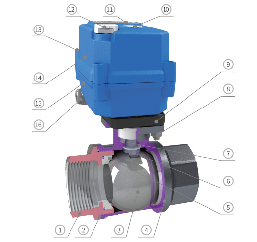
Main Components
| No. | Part | Material | Qty |
| 1 | Bonnet | Nickel-plated Brass/ 304/316L/2507 | 1 |
| 2 | Bonnet seal | EPDM/NBR/FPM ※3 | 1 |
| 3 | Ball | 304/316L/ Special wear-resistant ball/2507 | 1 |
| 4 | Body | Nickel-plated Brass/ 304/316L/2507 | 1 |
| 5 | Ball seat ※4 | PTFE | 2 |
| 6 | Stem | 304 / 316L / 2507 | 1 |
| 7 | Stem seal | EPDM/NBR/FPM ※3 | 1 |
| 8 | Mounting bracket screw | 304 | 4 |
| 9 | Mounting bracket | PA66 | 1 |
| 10 | Sight window | Transparent PC | 1 |
| 11 | Label | PC | 1 |
| 12 | Handwheel ※5 | POM | 1 |
| 13 | Top and bottom cover screw | 304 | 4 |
| 14 | Top cover | PC alloy ※6 | 1 |
| 15 | Bottom cover | PC alloy ※6 | 1 |
| 16 | Cable gland lock nut | PA66 | 1 |
※3 For gaseous media, wear-resistant PTFE is recommended.
※4 Other materials are customizable.
※5 30SJ series without handwheel.
※6 Avoid direct or indirect contact between PC and organic solvents such as toluene, xylene,ketones, dichloromethane, trichloromethane, and chloroform etc., due to corrosion resistance characteristics of PC materials.
| Dimensions-60S 【DN25-DN32】 | Dimensions-60SJ 【DN25-DN32】 |
 | |
Dimensions (mm)
| Body type | Connection type | DN | d | G1 | L1=L2 | L | H | H1 | H2 | F | W(kg) | |
| 60S | 60SJ | |||||||||||
| Full bore | Female thread | DN25 | 25 | G1" | 18 | 84 | 144.0 | 142.7 | 26.7 | 46.5 | 38 | - |
| DN32 | 32 | G1-1/4" | 20 | 97 | 152.8 | 151.5 | 31.5 | 50.5 | 48 | - | ||
Note:
1. Part dimension tolerances are in accordance with GB/T 1804-2000, Class m.
2. Assembly tolerance: ±2 mm.
3. Optional port threads: NPT, G, etc. Please specify when ordering.
Attention:
1. Due to batch-to-batch variations, data may be subject to minor changes. The physical product shall prevail. We reserve the right for modifications without prior notice!
2. For applications with limited installation space or strict dimensional requirements, please contact the relevant sales personnel.
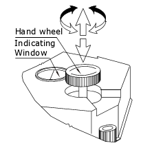
Instructions for Manual Override
Manual operation must be performed with power off. Refer to the manual for details.
※Subject to technical changes


