

Views: 0 Author: Site Editor Publish Time: 2026-09-14 Origin: Site


Valve selection directly impacts system stability, safety, and operational efficiency. Choosing between isolation and regulation changes fluid dynamics and system longevity. Misapplying a valve profile introduces severe engineering risks. Overspecifying a simple isolation point with a complex control unit increases maintenance burdens and adds unnecessary failure points. Underspecifying a dynamic control loop by installing a basic binary valve leads to process instability, severe water hammer, compromised safety interlocks, and premature mechanical wear. Engineers must conduct a rigorous technical evaluation to determine the exact requirements of their piping network. Understanding the fundamental mechanics of a modulating valve vs on-off value ensures system architecture aligns with operational demands. This evaluation requires analyzing flow dynamics, control loop feedback requirements, and the physical properties of the process media to choose between binary isolation and proportional control.
Operational Binary vs. Proportional Control: An on-off valve operates strictly at 0% or 100% open for system isolation, whereas a modulating valve adjusts continuously across the flow spectrum to maintain specific process setpoints.
Terminology Clarification: In industry literature, modulating valves are frequently referred to as "control valves," whereas on-off valves are categorized as isolation or block valves.
Actuation and Signal Complexity: Modulating valves require continuous control signals (e.g., 4-20mA, HART, or Fieldbus) and positioners for feedback, making them inherently more complex than the simple discrete signals used for on-off valves.
Cost and Maintenance Disparity: The initial procurement, calibration, and lifecycle maintenance costs of modulating valves are significantly higher; they should only be deployed where precise flow, temperature, or pressure regulation is strictly required.
Application Specificity: On-off valves are the industry standard for emergency shutdown (ESD), batch filling, and safety routing, while modulating valves are mandatory for dynamic process loops and continuous blending.
An on-off valve functions strictly as a binary device. Its operational parameters are limited to two distinct states: fully open to allow maximum flow or fully closed to stop flow entirely. This binary nature makes it the primary mechanism for positive isolation within a piping network. When the valve is open, the internal bore typically aligns flush with the pipeline. This full-port design minimizes pressure drop and allows fluid to pass without restriction. When closed, the sealing mechanism engages fully with the valve seats to prevent any fluid migration across the boundary.
The primary function of this valve type revolves around equipment protection, system maintenance, and unrestricted flow routing. Operators rely on these valves to isolate specific sections of a plant for maintenance without shutting down the entire facility. They serve as safety barriers in emergency shutdown systems, rapidly halting the flow of hazardous materials. Common mechanical profiles engineered for this specific duty include standard ball valves, gate valves, and high-performance butterfly valves. These designs prioritize a clear flow path and robust seating surfaces capable of withstanding high differential pressures when fully closed. For example, a trunnion-mounted ball valve provides excellent high-pressure isolation because the ball is anchored, allowing the line pressure to push the upstream seat against the ball for a tight seal.
A modulating valve provides proportional flow control. It possesses the mechanical and electrical capability to hold a position anywhere between 0% and 100% open. Rather than simply starting or stopping flow, these valves throttle the process media to achieve specific downstream conditions. They act as the final control element in a closed-loop control system. A programmable logic controller (PLC) or distributed control system (DCS) continuously monitors process variables like temperature, pressure, or flow rate. The controller compares the actual variable to the desired setpoint, calculates the error using a Proportional-Integral-Derivative (PID) algorithm, and sends a corresponding signal to the valve to adjust its position.
Mechanical profiles for modulating duties are specifically engineered to handle the harsh realities of continuous throttling. Typical designs include globe valves, v-port ball valves, and eccentric plug valves. The internal trim of these valves is highly specialized. When fluid is forced through a partially open valve, velocity increases while pressure drops. This physical change frequently leads to cavitation or severe aerodynamic noise. Modulating valve trims feature customized flow characterization, anti-cavitation cages, and noise-attenuating designs to manage these destructive fluid dynamics. A cage-guided globe valve, for instance, uses a perforated cylinder to divide the flow into smaller streams, reducing the kinetic energy and preventing cavitation bubbles from imploding against the valve body.
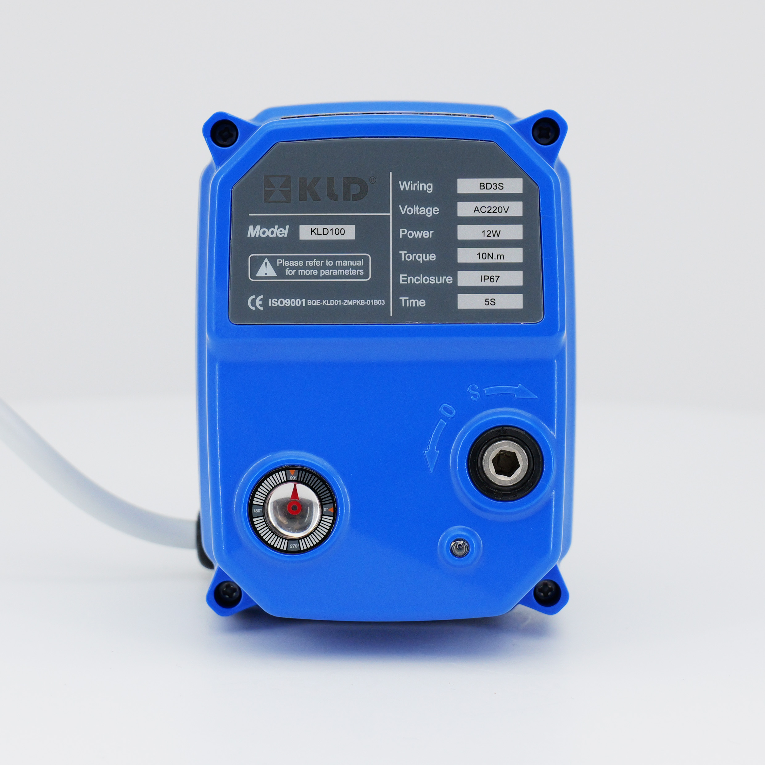
| Technical Feature | On-Off Valve | Modulating Valve |
|---|---|---|
| Primary Function | Positive isolation and flow routing | Proportional control of process variables |
| Operating States | 0% (Closed) or 100% (Open) | Any position between 0% and 100% |
| Actuation Signal | Discrete (24V DC, 120V AC, Pneumatic pulse) | Analog (4-20mA) or Digital (HART, Fieldbus) |
| Feedback Mechanism | Limit switches or proximity sensors | Electro-pneumatic or digital positioner |
| Typical Leakage Class | ANSI Class VI (Bubble-tight) | ANSI Class III, IV, or V (Engineered leakage) |
The most defining technical contrast lies in the range of motion. An On-Off Valve operates on discrete end-states. It transitions from fully seated to fully unseated, offering no reliable intermediate positioning. Attempting to hold a standard binary valve at a 50% open position results in erratic flow and rapid mechanical degradation. The fluid velocity will erode the soft seats, destroying the valve's ability to isolate. Modulating valves deliver high-resolution positioning. They make micro-adjustments—sometimes as small as 0.1% of total travel—to fine-tune the fluid passage.
Flow characteristics matter exclusively for modulating applications. These characteristics define the mathematical relationship between the valve's percentage of travel and its flow capacity (Cv). A linear characteristic provides a flow rate directly proportional to valve travel. An equal percentage characteristic ensures that equal increments of valve travel produce equal percentage changes in the existing flow. This specific curve is highly effective for maintaining control loop stability across varying pressure drops. Quick-opening characteristics provide maximum flow with minimal initial travel, occasionally used in specific venting applications. Binary valves do not utilize these engineered flow curves because they are not designed to throttle.
Signal requirements dictate the electrical architecture of the valve installation. Binary isolation valves rely on discrete voltage or pneumatic pulses. A simple 24V DC or 120V AC signal energizes a solenoid, which directs instrument air to open or close the actuator. The control system only needs to issue a basic "run" or "stop" command. Modulating valves require analog or digital communication protocols. The industry standard remains the 4-20mA analog signal, where 4mA represents fully closed and 20mA represents fully open. Modern installations frequently utilize digital protocols like HART, Foundation Fieldbus, or Profibus. These digital networks transmit the primary control signal alongside extensive diagnostic data.
Actuator mechanics differ significantly based on the duty cycle. Simple pneumatic or electric actuators for isolation valves sit dormant for long periods. They actuate, reach their end state, and hold pressure. Modulating electric actuators require continuous duty ratings. They handle constant micro-adjustments dictated by the PID controller without the motor overheating. These actuators feature specialized gearing, robust heat dissipation, and high-frequency start/stop capabilities to manage the relentless hunting required to maintain tight process setpoints. Pneumatic modulating actuators use rolling diaphragms instead of standard pistons to eliminate stick-slip friction during small movements.
Stroke time parameters serve entirely different operational goals. Binary valves often require rapid actuation capabilities. In an emergency shutdown scenario, an isolation valve might need to stroke from fully open to fully closed in under one second to isolate a pipeline rupture or stop a runaway chemical reaction. Pneumatic actuators equipped with quick-exhaust valves dump air instantly to achieve these high-speed requirements. Rack and pinion actuators are frequently selected for these fast-acting quarter-turn applications.
Modulating valves utilize deliberate, dampened stroke speeds. Rapid movement in a control loop causes the process variable to overshoot the setpoint. This leads to continuous oscillation and system instability. Actuators on modulating valves are geared or restricted to move smoothly and predictably. This controlled speed allows the PID controller to read the process reaction, recalculate the error, and issue updated commands without inducing hydraulic shock or erratic flow fluctuations.
Verifying valve status requires different instrumentation depending on the valve type. Isolation valves use simple limit switches or proximity sensors. These discrete devices trigger only when the valve stem reaches the absolute end of its travel. They send a binary confirmation back to the control room that the valve is definitively open or closed. If the valve sticks at 95% open, the limit switch will not engage, alerting the operator to a mechanical fault.
Modulating setups mandate the use of valve positioners. A positioner acts as a localized control loop mounted directly on the valve. It receives the command signal from the main DCS (e.g., 12mA for 50% open) and compares it to the actual physical position of the valve stem using a mechanical linkage or non-contact magnetic sensor. If the stem is only at 48%, the positioner automatically adjusts the pneumatic output to the actuator until the physical position perfectly reconciles with the command signal. This feedback loop eliminates errors caused by packing friction, varying process pressures, or aerodynamic forces acting on the valve trim.

Certain industrial processes make modulation strictly non-negotiable. Heat exchangers require exact temperature control to prevent product degradation. This demands a valve capable of continuously adjusting the flow of steam or cooling water. Continuous chemical dosing systems rely on proportional control to maintain exact pH levels or mixture ratios. Pressure reducing stations must instantly adapt to fluctuating upstream pressures to deliver a constant downstream output. In these scenarios, a binary valve would cause violent swings in the process variable, destroying product quality and stressing the piping.
Process stability heavily depends on the mechanical resolution of the modulating assembly. Deadband refers to the range through which the input signal can be varied without initiating any observable change in valve position. Hysteresis describes the difference in valve position for a given signal depending on whether the signal is increasing or decreasing. High-quality modulating valves minimize deadband and hysteresis. This ensures that even the smallest controller output results in a precise physical adjustment, keeping the process variable locked onto the setpoint.
When the operational priority shifts from regulation to absolute containment, binary valves become mandatory. Emergency Shutdown Valves (ESDV) are the critical final line of defense in hazardous environments. They sit fully open during normal operations and must close flawlessly upon receiving a trip signal. Block-and-bleed systems utilize a sequence of binary valves to guarantee zero fluid migration into a section of pipe undergoing maintenance. Tank farm routing requires clear, unrestricted flow paths to move massive volumes of product between storage vessels without pressure loss.
Safety compliance standards dictate strict shutoff classifications for these applications. Safety Integrity Level (SIL) ratings evaluate the reliability of a safety instrumented function. Valves used in SIL-rated loops must demonstrate exceptionally low probabilities of failure on demand. The simplicity of a binary actuator combined with a robust isolation valve provides the predictable, repeatable performance required to meet stringent safety certifications.
The expectation of internal sealing differs drastically between the two valve categories. Isolation valves are designed to provide bubble-tight shutoff. Under the ANSI/FCI 70-2 standard, these valves typically meet Class VI requirements. They utilize resilient soft seats made of PTFE, PEEK, or elastomers to ensure zero visible leakage even under high differential pressure. This absolute seal prevents cross-contamination and protects personnel during downstream maintenance.
Modulating control valves prioritize throttling performance over absolute sealing. Their internal trims are often constructed entirely of hardened metals like Stellite to withstand the erosive forces of high-velocity fluids and cavitation. Metal-to-metal seating surfaces rarely achieve bubble-tight status. Modulating valves typically carry ANSI Class III, IV, or V leakage rates. A Class IV valve, for example, allows 0.01% of the rated valve capacity to leak past the seat when fully closed. These engineered leakage rates are acceptable because the valve's primary job is dynamic control, not dead-end isolation. If tight shutoff is required in a control loop, engineers install a dedicated binary isolation valve immediately upstream of the modulating valve.
Modern Distributed Control Systems (DCS) and Programmable Logic Controllers (PLC) integrate both valve types, but the data exchange varies. Integrating a binary valve requires minimal I/O capacity. You typically need one digital output to command the solenoid and two digital inputs to read the open/closed limit switches. This simplicity makes scaling up a facility with hundreds of isolation points straightforward and reliable.
Smart modulating valves offer significant data-gathering advantages. Digital positioners utilizing HART or Fieldbus protocols transmit a wealth of diagnostic information back to the control room. Maintenance teams monitor total stem travel, reversal counts, supply pressure variations, and internal friction analysis. This data enables predictive maintenance strategies. Technicians identify degrading packing or actuator wear long before the valve actually fails in the field. While this integration requires more complex programming and higher bandwidth, the operational intelligence gained is invaluable for critical control loops.
Installing a modulating valve where simple isolation is sufficient represents a significant engineering misstep. Utilizing a complex control valve with a digital positioner and specialized trim for a basic tank-filling operation introduces unnecessary points of failure. The continuous-duty actuator and sensitive pneumatic relays require cleaner instrument air and more frequent calibration than a simple on-off solenoid. This overspecification complicates the control architecture and increases the likelihood of unplanned downtime due to instrument malfunction.
Mitigation requires a strict Piping and Instrumentation Diagram (P&ID) and PID loop review prior to specification. Engineers must verify whether proportional control is actually dictated by the process chemistry or thermodynamics. If the process only requires moving fluid from point A to point B without regulating the flow rate in real-time, a standard isolation valve is the correct technical choice.
Attempting to use a fast-acting binary valve for pseudo-control or throttling creates severe mechanical and hydraulic hazards. Standard ball or gate valves possess non-linear flow characteristics. Opening them slightly results in a massive, unpredictable surge of fluid. Throttling a standard soft-seated valve causes the high-velocity fluid to erode the polymer seats, permanently destroying the valve's ability to shut off tightly. Rapidly closing a binary valve against high flow rates induces severe water hammer. This sudden velocity change sends destructive shockwaves through the piping system that can rupture joints and damage pumps.
To mitigate these fluid dynamic issues, engineers must implement stroke-speed controls. Installing pneumatic exhaust restrictors on binary actuators slows the closing speed, dissipating the kinetic energy of the fluid and preventing water hammer. If the process requires gradual flow velocity changes or intermediate positioning, upgrading to a properly sized modulating valve with characterized trim is the only safe engineering solution.
Modulating valves rely heavily on accurate signal transmission. Analog 4-20mA signals are susceptible to Electromagnetic Interference (EMI) and Radio Frequency Interference (RFI) generated by nearby variable frequency drives, large motors, or high-voltage power lines. Signal noise causes the valve positioner to read fluctuating commands, resulting in erratic valve movement and unstable flow rates. Mechanical linkages within the positioner experience calibration drift over time due to vibration and thermal cycling.
Mitigating signal interference requires strict adherence to instrumentation wiring standards and routine maintenance checks. Follow these steps to ensure signal integrity:
Verify shield grounding at the DCS cabinet to isolate the analog signal from external noise.
Inspect positioner linkages and feedback arms for mechanical wear or loose connections.
Run a step-response test to check for excessive hysteresis or deadband in the valve assembly.
Upgrade the control architecture to digital communication protocols to eliminate analog signal degradation entirely.
Program smart positioners to run self-calibration routines during scheduled downtime.
Audit your facility P&ID to clearly separate critical isolation points from dynamic control loops before specifying new equipment.
Calculate the required flow coefficient (Cv) for both minimum and maximum flow conditions to ensure any selected modulating valve operates within its optimal control range.
Specify ANSI Class VI shutoff for any valve designated for emergency shutdown, block-and-bleed, or maintenance isolation.
Upgrade analog 4-20mA control loops to digital HART or Fieldbus protocols if your facility experiences frequent signal interference or requires advanced predictive diagnostics.
A: No. Using an on-off valve, like a standard gate or ball valve, for throttling causes premature seat wear, severe cavitation, and poor flow control. These valves lack engineered flow characteristics, meaning slight movements cause unpredictable flow surges. The high-velocity fluid will quickly erode the sealing surfaces, destroying the valve's ability to provide positive isolation.
A: The industry standard remains the 4-20mA analog signal, where 4mA commands the valve fully closed and 20mA commands it fully open. Modern industrial facilities increasingly utilize digital alternatives like HART, Foundation Fieldbus, and Profibus, which transmit the control signal alongside valuable diagnostic and calibration data.
A: Modulating valves require highly specialized components. They utilize custom-machined throttling trims designed to mitigate cavitation and noise. They require continuous-duty actuators capable of constant micro-adjustments without overheating, and they must incorporate electro-pneumatic or digital positioners to provide accurate closed-loop mechanical feedback.
A: Generally, no. While some modulating valves achieve tight shutoff, their primary design focuses on flow control. They often utilize metal-to-metal seats to withstand erosive throttling, resulting in ANSI Class IV or V leakage rates. Dedicated on-off valves with soft seats are preferred for critical, bubble-tight isolation.
A: Converting requires significant technical modifications. You must replace the simple actuator with a continuous-duty model and add a digital positioner for feedback. Most importantly, you must verify that the valve's internal trim is suitable for proportional flow. Standard binary trims suffer severe cavitation damage if forced to throttle continuously.


