

Views: 0 Author: Site Editor Publish Time: 2026-09-14 Origin: Site


Imprecise fluid control drains operational budgets and accelerates equipment wear across industrial facilities. Binary flow control operates strictly in fully open or fully closed states. This on-off methodology completely fails to maintain dynamic set points for temperature, pressure, or flow rate under fluctuating system loads. Process variables constantly shift. You need a mechanical solution capable of continuous, proportional adjustment to match these shifting demands.
Understanding the precise mechanics of a modulating valve is the first step in specifying the correct control architecture for your facility. This foundational knowledge allows engineers to optimize process efficiency, stabilize control loops, and mitigate long-term maintenance liabilities. Selecting the right components prevents catastrophic pipeline failures and ensures precise environmental or chemical regulation.
A modulating valve adjusts flow proportionally between 0% and 100% using a continuous control signal, enabling precise, automated maintenance of system set points.
Reliable modulation requires the seamless integration of three distinct components: the valve body (fluid regulation), the actuator (motive force), and the positioner (feedback accuracy).
Selecting the correct valve type (globe, V-port ball, butterfly) requires balancing the required flow coefficient (Cv) against pressure drop, fluid properties (liquid, gas, steam), and inherent flow characteristics.
Improper sizing or component selection introduces critical implementation risks, including cavitation, flashing, stiction, and control loop hunting.
Binary control relies on on-off valves. These valves only exist in two states: 100% open or 0% closed. This limitation causes severe mechanical stress within piping networks. Rapidly closing a standard isolation valve halts fluid momentum instantly. This sudden deceleration generates a hydraulic shock wave known as water hammer. The kinetic energy of the moving fluid converts into massive pressure spikes. These spikes rupture seals, destroy instrumentation, and tear piping supports from their anchors. We see this frequently in poorly designed cooling water loops where operators use gate valves for throttling.
Furthermore, binary control fails entirely in applications requiring continuous variable adjustment. Consider a heat exchanger designed to output fluid at exactly 150°F. If the steam supply valve only cycles between fully open and fully closed, the output temperature will wildly oscillate. The system will constantly overshoot and undershoot the target set point. This erratic behavior ruins product quality and wastes immense amounts of thermal energy.
Dynamic systems demand proportional responses. Operational requirements dictate the use of modulation when tight tolerances are mandatory. If a chemical reaction requires a feed rate accurate to within 1%, binary control cannot succeed. You must utilize continuous adjustment.
Variable load demands also necessitate modulation. Downstream demand rarely remains static. As consumers draw more water from a municipal system, or as a building requires more cooling during peak afternoon hours, the flow rate must scale accordingly. Gradual flow adjustment protects sensitive downstream equipment. Slowly ramping up pressure prevents sudden surges from damaging delicate filtration membranes or over-spinning turbine blades.
Commercial building temperatures fluctuate based on occupancy levels, solar heat gain, and external weather conditions. A modulating valve automatically controls these interior spaces. It fine-tunes the flow of chilled or hot water through the coils of air handling units. As the room temperature approaches the thermostat set point, the valve gradually closes. It reduces the water flow to match the exact thermal load. This precise throttling prevents uncomfortable temperature swings and drastically reduces the energy consumed by chiller plants and boilers. In large campus environments, hundreds of these valves work in tandem to balance the entire hydronic network.
Chemical reactions require strict environmental controls to remain safe and productive. Volatile liquids and reactive gases demand exact pressure and flow rates. Modulating control valves maintain these parameters. They ensure safe, stable chemical reactions inside pressurized reactors. A slight deviation in catalyst flow can ruin an entire production batch or trigger a dangerous thermal runaway. Continuous modulation prevents these costly excursions by adjusting flow rates in real-time based on sensor feedback. We often install specialized alloy valves in these units to handle highly corrosive feedstocks while maintaining tight control tolerances.
Power plants rely on the precise delivery of high-pressure steam to spin massive turbines. Modulating valves regulate this steam over part or all of their travel. They optimize turbine efficiency by matching the steam flow directly to the electrical grid demand. During startup sequences, these valves open incrementally. This slow introduction of steam warms the piping gradually. Precise modulation protects power generation infrastructure from thermal shock, pipe distortion, and catastrophic over-speed conditions. Boiler feedwater systems also rely heavily on these valves to maintain drum levels under rapidly changing load conditions.
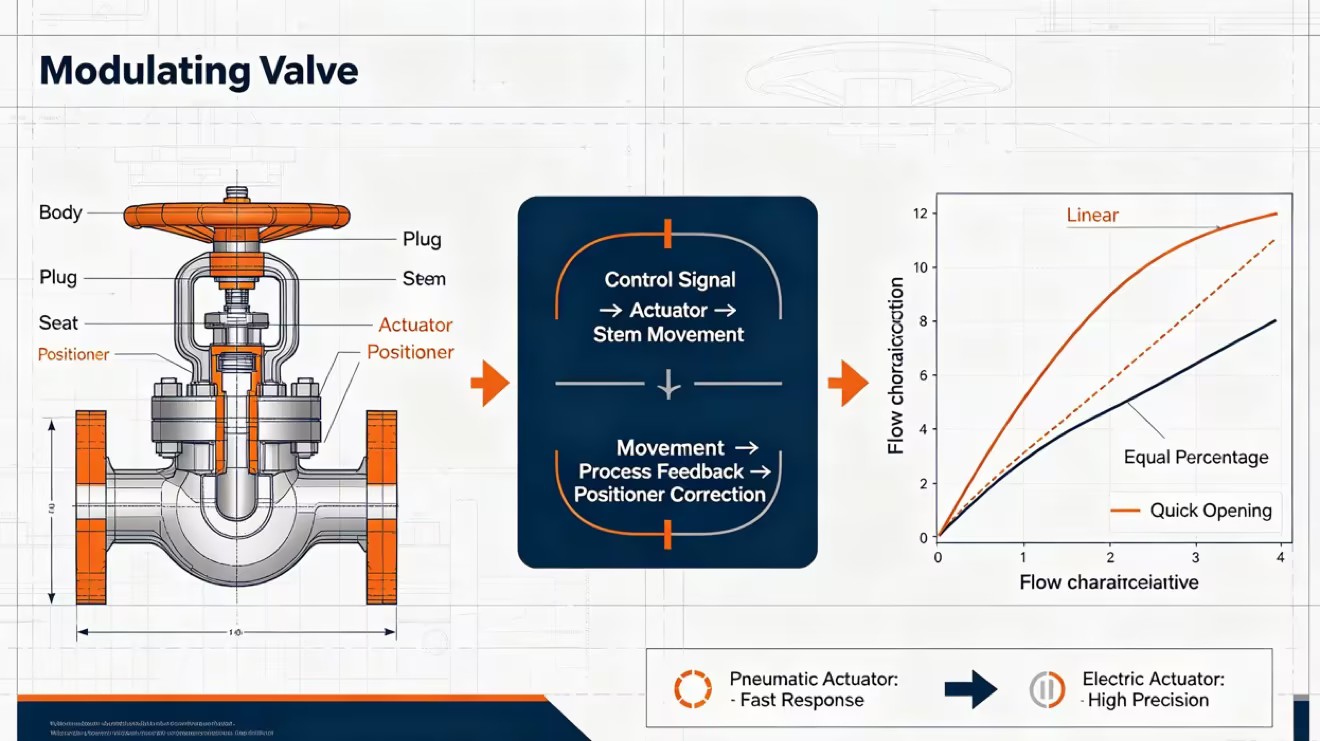
The valve body serves as the primary pressure boundary. It contains the internal wetted parts, collectively known as the trim. The trim typically includes the plug, the seat ring, and the valve stem. These components physically restrict or permit fluid passage. As the stem moves, the plug moves closer to or further from the seat.
The specific shape of the trim dictates the flow profile. A flat disk plug provides a quick-opening characteristic. A parabolic or contoured plug yields a linear or equal percentage flow characteristic. Engineers often use cage-guided trim for high-pressure applications. The cage acts as a guiding cylinder for the plug, providing stability against aggressive fluid turbulence and reducing mechanical vibration.
The actuator provides the physical motive force required to move the valve stem over its stroke. It translates a control signal into mechanical motion. Industry utilizes several distinct actuator mechanisms:
Pneumatic Actuators: These utilize compressed air acting against a flexible diaphragm or a rigid piston. They offer rapid response times and high thrust. They easily incorporate mechanical springs to drive the valve to a safe position if air pressure is lost.
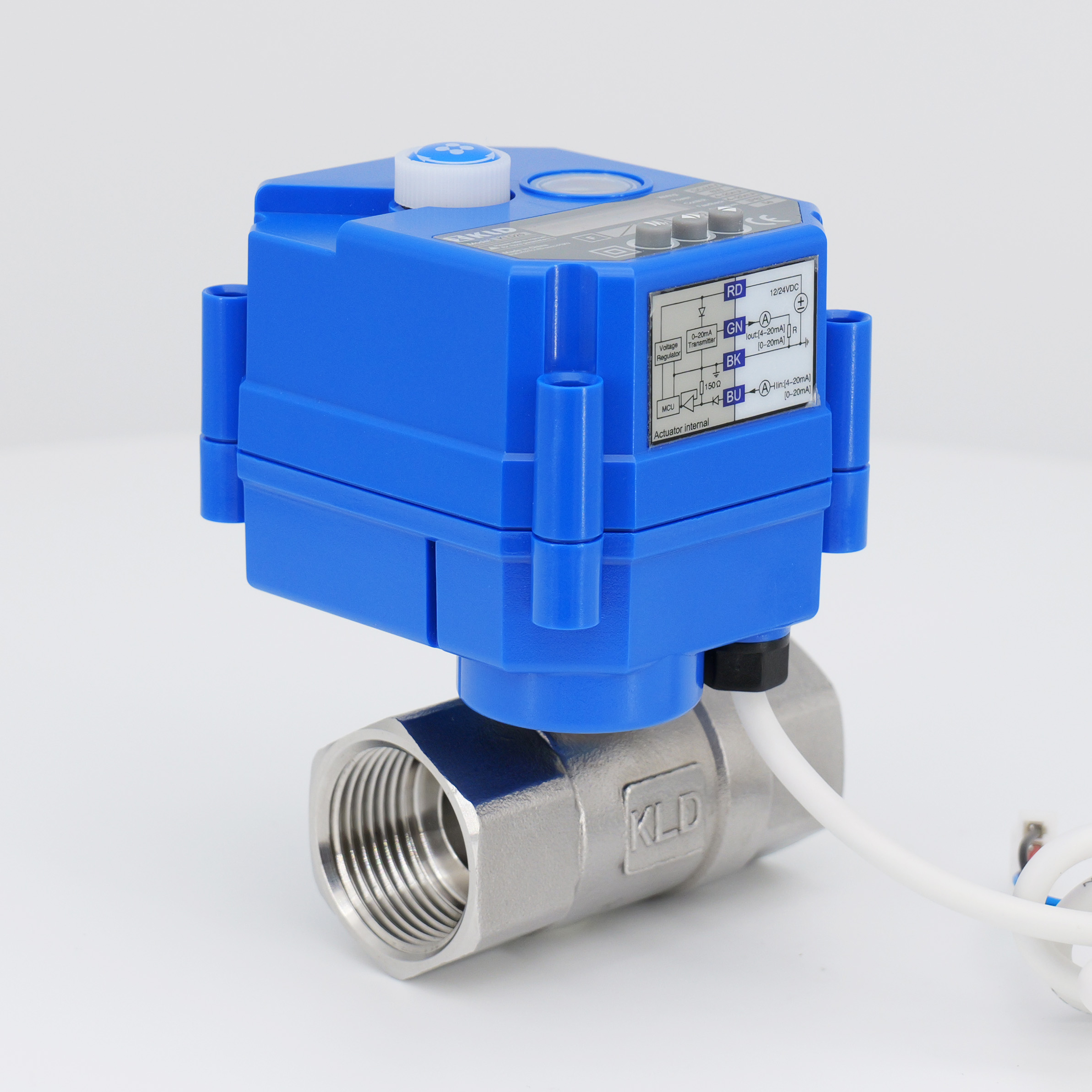
Electric Actuators: These employ electric motors coupled with gearboxes. They provide high precision and eliminate the need for a plant-wide compressed air network. They are ideal for remote locations.
Electro-Hydraulic Actuators: These combine electrical control signals with self-contained hydraulic power. They deliver massive thrust capabilities required for exceptionally large valves or extreme pressure drops.
The positioner acts as the brain of the modulating assembly. It mounts directly to the actuator. The positioner reads the incoming control signal from the plant network. It then mechanically or digitally compares this command signal to the actual physical position of the valve stem.
If pipeline pressure pushes against the plug and forces it out of alignment, a discrepancy occurs. The positioner detects this error immediately. It applies corrective force by adding or venting air pressure in the actuator. This closed-loop feedback eliminates deadband. It ensures exact stem placement regardless of fluctuating dynamic forces inside the pipe.
Automated control requires standardized communication protocols. The positioner must understand what the central control system wants it to do. Industry-standard inputs command the valve position. Analog signals, primarily 4-20mA, remain the most common. A 4mA signal typically commands the valve to close fully, while 20mA commands it to open fully.
Modern facilities utilize digital fieldbus protocols like HART, Profibus, or Foundation Fieldbus. These digital signals carry the primary position command alongside rich diagnostic data. They interface seamlessly with Programmable Logic Controllers (PLCs) or Distributed Control Systems (DCS). The central processor calculates the required output based on PID algorithms and sends the exact command to the positioner for fully automated control.
Engineers universally consider globe valves the industry standard for high-precision throttling. The internal fluid path forces the media to change direction twice. This tortuous path creates a naturally high pressure drop. Globe valves handle severe service conditions exceptionally well. They offer tight shutoff capabilities and excellent rangeability. Their robust design allows them to withstand the high velocities and turbulence associated with aggressive pressure reduction. We frequently specify globe valves for boiler feedwater and high-pressure steam letdown stations where precise control is non-negotiable.
High-capacity flow control applications often utilize V-port ball valves. A standard ball valve features a circular port. As it opens, the flow area changes non-linearly, resulting in poor throttling control. The V-port design solves this issue. Manufacturers machine a "V" shaped notch into the ball. As the ball rotates, this notch exposes the flow area gradually. This geometry allows for a highly linear flow characteristic. V-port valves provide high flow capacity alongside precise control. They excel in handling fibrous slurries, paper pulp, and clean fluids. The shearing action of the V-notch also prevents solid particles from jamming the mechanism.
Large-diameter piping requires cost-effective solutions. Butterfly valves fit this requirement perfectly due to their compact face-to-face dimensions and lower material costs. However, standard concentric butterfly valves struggle with modulation. They suffer from high operating torques and poor resolution near the closed position.
High-performance butterfly valves utilize double or triple offset designs. These offsets move the pivot point of the disc away from the centerline. This reduces seat friction and improves throttling accuracy. Despite these improvements, they still possess a limited effective control range. You typically only modulate them between 20° and 70° of rotation. Operating outside this range often results in erratic flow control and accelerated seat wear.
Accurate sizing dictates control performance. The flow coefficient (Cv) represents the mathematical relationship between flow rate, specific gravity, and pressure drop. By definition, one Cv equals one US gallon of water per minute at 60°F flowing through a valve with a one psi pressure drop. Calculating the required Cv is the most important step in valve specification.
Oversized valves cause severe operational issues. An oversized valve must operate very close to its seat to restrict flow adequately. This proximity causes the control loop to hunt, constantly oscillating open and closed. It also accelerates trim wear due to high-velocity fluid squeezing through a tiny gap. Conversely, undersized valves cannot pass the required flow rate. They cause excessive pressure loss and generate dangerous fluid velocities, leading to rapid erosion and unacceptable noise levels.
Theoretical performance often differs from real-world application. The inherent flow characteristic describes the behavior of the valve under a perfectly constant pressure drop. Manufacturers test and publish these inherent curves. However, in a dynamic piping system, the pressure drop across the valve varies as the flow rate changes. This dynamic behavior defines the installed flow characteristic.
| Flow Characteristic | Inherent Behavior (Constant Pressure Drop) | Best Application Use Case |
|---|---|---|
| Linear | Flow rate is directly proportional to valve travel (e.g., 50% open = 50% flow). | Liquid level control, systems with constant pressure drops. |
| Equal Percentage | Equal increments of valve travel produce equal percentage changes in existing flow. | Temperature control, systems where pressure drop varies heavily with flow. |
| Quick Opening | Maximum flow is achieved rapidly with minimal initial valve travel. | On-off service, safety relief, or rapid batch filling operations. |
Fluid properties dictate material selection. Corrosive fluids will rapidly destroy standard carbon steel components. You must select body and trim materials based on the chemical makeup of the media. Common options include 316 stainless steel, duplex alloys, or specialized materials like Hastelloy and Monel for severe acid service.
Temperature extremes heavily influence selection. Cryogenic applications require austenitic stainless steels that retain toughness at sub-zero temperatures. High-temperature steam applications require chrome-moly alloys to prevent creep and deformation. Always adhere strictly to industry standards published by organizations like ASME, API, and NACE. Compliance ensures pressure boundary integrity and protects plant personnel.
Selecting the motive force involves distinct operational trade-offs. Pneumatic actuators deliver exceptionally rapid response speeds. They react to control signals almost instantly. They also easily incorporate mechanical spring-return mechanisms. If the plant loses power or air supply, the heavy internal spring forces the valve to a predetermined safe position. However, pneumatic systems require a reliable, clean, and dry compressed air infrastructure. Moisture in the air lines will destroy positioner pneumatics.
Electric actuators simplify installation. They only require electrical power routing and signal cables. They eliminate the need for expensive air compressors and pneumatic tubing. Electric actuators provide incredibly precise positioning. However, they generally actuate slower than pneumatic equivalents. Achieving fail-safe capabilities requires battery backups or complex super-capacitors, which introduce additional electronic failure points.
Specifying standard, low-tier equipment often reduces initial project capital expenditures. However, this approach frequently proves detrimental in continuous process environments. Severe-service applications quickly degrade standard components. A cheaper valve might suffer trim erosion within six months, forcing an unplanned plant shutdown.
Investing in robust modulating control valves equipped with advanced smart positioners yields massive operational dividends. Smart diagnostics monitor valve friction and air consumption in real-time. They predict packing failures before fugitive emissions occur. Precise modulation reduces wasted thermal energy in heating loops. Minimizing process variability directly increases product yield and drastically reduces expensive, unplanned downtime.
Severe pressure drops trigger destructive hydrodynamic phenomena in liquid applications. Flashing occurs when the fluid pressure drops below its vapor pressure inside the valve and remains below that threshold downstream. The liquid boils into a vapor state. This high-velocity vapor carries liquid droplets that act like sandblasters, eroding the downstream piping.
Cavitation happens when the pressure drops below the vapor pressure but recovers above it downstream. Vapor bubbles form in the low-pressure zone. As the pressure recovers, these bubbles violently collapse or implode. These micro-implosions generate localized shock waves that tear microscopic pieces of metal from the valve trim. Mitigation strategies include specifying multi-stage anti-cavitation trims. These specialized cages break the massive pressure drop into smaller, manageable stages. Utilizing hardened materials like Stellite overlays also resists mechanical erosion.
Mechanical friction severely degrades control loop performance. Stiction, or static friction, prevents the valve stem from moving smoothly. When the controller sends a small signal change, the stem sticks in place due to tight packing. The controller increases the signal until the actuator force overcomes the static friction. The stem then suddenly jumps past the desired set point. This causes endless loop oscillation.
Deadband represents mechanical slop in the linkages between the actuator, stem, and positioner. The control signal changes, but the valve plug does not move immediately because the mechanical connections are loose. Smart positioners mitigate these issues. They apply aggressive, calculated pneumatic bursts to overcome stiction instantly. Selecting low-friction PTFE packing balances strict emission control requirements with smooth stem travel.
Process safety demands rigorous upkeep. Modulating valves are highly dynamic mechanical devices operating under extreme stress. They require routine calibration to ensure the zero and span settings perfectly match the incoming control signals. A valve that thinks 4mA means 5% open will leak constantly when commanded to close.
Routine packing adjustments prevent dangerous fugitive emissions. Advanced diagnostic monitoring tracks valve signature curves over time. By comparing current friction levels and air consumption against baseline data recorded during commissioning, maintenance teams can identify internal wear. This predictive data highlights problems before catastrophic failure occurs, maintaining the highest standards of process safety and reliability.
A modulating valve remains a non-negotiable requirement for industrial systems demanding dynamic, continuous control. Binary on-off valves simply cannot manage precise process variables like temperature, pressure, and flow rate under fluctuating loads. Precise modulation protects infrastructure, optimizes energy usage, and ensures product quality. Base your initial selection on rigorous engineering data. Determine the exact required Cv based on flow rates. Identify the fluid state as liquid, gas, or steam to predict hydrodynamic risks. Calculate the maximum allowable pressure differential to select the right trim style. Finally, align your actuator choice with your existing plant infrastructure.
To ensure successful implementation, execute the following next steps:
Consult with a specialized valve engineer to run exact sizing calculations across your minimum, normal, and maximum flow conditions.
Perform computational fluid dynamics (CFD) analysis for high-pressure drop applications to predict and mitigate cavitation or flashing risks.
Finalize actuator and positioner compatibility to guarantee seamless digital integration with your existing DCS or PLC network.
Establish a baseline diagnostic signature during initial commissioning to guide all future predictive maintenance schedules.
A: An on-off valve operates exclusively in binary states: fully open or fully closed. It cannot regulate flow incrementally. A modulating valve provides continuous proportional control. It adjusts its position anywhere between 0% and 100% across its travel to precisely regulate flow, pressure, or temperature based on a variable control signal.
A: Automated control systems typically command these valves using analog signals like 4-20mA or 0-10V DC. Modern industrial environments frequently utilize digital fieldbus protocols, including HART, Profibus, or Foundation Fieldbus. These digital protocols transmit the precise position command alongside valuable diagnostic and health data.
A: Sizing relies on calculating the flow coefficient (Cv). This formula uses your maximum, normal, and minimum flow rates, the specific gravity of the fluid, and the exact pressure drop across the valve. Accurate pressure drop data is critical; incorrect data leads to oversized or undersized valves.
A: Standard concentric butterfly valves perform poorly in modulating applications due to high seating friction and non-linear flow characteristics. For throttling, you must use high-performance butterfly valves featuring double or triple offset designs. Even then, their effective modulating range is limited to between 20 and 70 degrees of rotation.
A: Hunting, or continuous oscillation around a set point, occurs for three main reasons. The valve may be oversized, forcing it to operate too close to the seat. The PID control loop tuning may be too aggressive. Finally, severe mechanical stiction can cause the valve stem to jump past the target position.
A: A positioner is a feedback device mounted to the actuator. It receives the control signal and compares it to the actual physical position of the valve stem. It is necessary because it automatically adjusts the actuator force to overcome pipeline pressure and friction, ensuring the stem matches the exact commanded position.
A: With a linear characteristic, flow capacity increases directly proportional to valve travel. A valve 50% open yields 50% flow. With an equal percentage characteristic, equal increments of valve travel produce equal percentage changes in the existing flow rate. Equal percentage is typically used for temperature control or systems with varying pressure drops.


