

Views: 0 Author: Site Editor Publish Time: 2026-09-14 Origin: Site


Poor flow control drains resources rapidly across industrial and commercial facilities. It causes severe energy waste, process instability, and premature equipment wear. Catastrophic system failures often start with a single mismatched component unable to handle dynamic fluid conditions. Selecting a msdulating value extends far beyond simply matching pipe sizes and flange ratings. It requires a precise alignment of fluid dynamics, pressure drops, material compatibility, and actuator response. Without these elements working together, achieving stable, repeatable control is physically impossible. This guide provides a systematic, engineering-based framework for evaluating, sizing, and specifying the correct Modulating Valve. You will learn how to optimize process loops, prevent destructive fluid phenomena, and ensure long-term reliability across demanding applications.
Sizing is Non-Negotiable: Oversizing is the most common cause of poor control and valve hunting; accurate Flow Coefficient (Cv) calculation is mandatory.
Application Dictates Valve Type: Globe valves offer unmatched precision, while V-port ball and high-performance butterfly valves provide cost-effective solutions for specific flow characteristics and larger pipe diameters.
Actuation Drives Accuracy: The physical valve body is only as effective as the actuator and smart positioner driving its modulation.
Context Matters: Selection criteria shift dramatically depending on whether the application is a heavy industrial process or a commercial HVAC/hydronic system.
Risk Mitigation Extends Lifespan: Proactively addressing differential pressure prevents destructive phenomena like cavitation, flashing, and excessive aerodynamic noise.
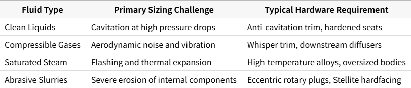
Before evaluating hardware options, you must define the exact fluid conditions of your system. Gather precise data on the fluid type passing through the line. You need to know if the system handles a liquid, gas, steam, or abrasive slurry. Determine the specific gravity, dynamic viscosity, and operating temperature ranges. These variables dictate how the fluid behaves under varying pressure states. Specific gravity directly alters the mass flow calculations, while viscosity impacts the Reynolds number. Highly viscous fluids like heavy oils or polymers require entirely different sizing approaches compared to water. Next, map out the volumetric or mass flow rates. You must identify the absolute minimum, normal operating, and absolute maximum flow rates. These numbers establish the required control range for the equipment. Failing to establish this baseline leads to immediate specification errors. You cannot control what you have not accurately measured.
Modulating valves provide continuous throttling capabilities. They use internal closure elements to adjust the flow area dynamically based on an external signal. On-off valves strictly isolate flow, remaining either fully open or fully closed. A common misconception exists regarding standard ball and plug valves. While standard versions perfectly suit on-off isolation applications, they fail at precise throttling. Characterized versions are specifically engineered for modulation. Success in modulation requires meeting strict performance criteria. You must define acceptable deadband limits, which dictate the minimum signal change required to initiate physical movement. You must also establish hysteresis tolerances, ensuring the valve reaches the exact same position regardless of whether it is opening or closing. Finally, you need to select the correct inherent flow characteristic based on the process loop dynamics.
Linear: Flow capacity increases linearly with valve travel. This profile works best for liquid level control systems where the pressure drop remains relatively constant.
Equal Percentage: Equal increments of travel produce equal percentage changes in the existing flow. This is the standard choice for most heating, cooling, and pressure control loops where system pressure drops vary significantly.
Quick Opening: Maximum flow is reached rapidly within the first 20% of travel. While mostly used for on-off isolation, it occasionally serves specific pressure relief applications.
Pipe diameter acts as a primary physical filter for equipment selection. It limits your available options based on geometry and fluid velocity. Globe valves and characterized ball valves dominate smaller piping networks. They are typically preferred for process lines under four inches in diameter. High-performance butterfly valves become the standard for large-diameter piping. Once you exceed six to eight inches, the weight and physical footprint of globe valves become prohibitive. Butterfly valves offer a highly practical solution for these larger lines. However, you must ensure the fluid velocity remains within acceptable limits. Liquid velocity should generally stay below 15 feet per second to prevent severe erosion of the downstream piping. Gas velocity must remain below Mach 0.3 to prevent excessive noise generation. Always check the pipe schedule, as thicker walls reduce the internal diameter and increase the actual fluid velocity.
Globe valves force fluid through a restricted, tortuous flow path. This internal design offers superior control and exceptionally high rangeability. It allows for exact positioning of the plug relative to the seat ring. They represent the benchmark for throttling precision in critical processes. You can specify unbalanced or pressure-balanced trims depending on the actuator force available. Balanced plugs use fluid pressure to equalize forces across the closure element, allowing you to use significantly smaller actuators. Cage-guided trims provide massive stability against lateral fluid forces, preventing vibration and stem wear in high-velocity applications. However, globe valves come with notable trade-offs. You will face a larger physical footprint and heavier weight. They also generate a significantly higher inherent pressure drop compared to rotary alternatives, which demands more pumping power from the system.
V-port ball valves feature a characterized "V" notch machined directly into the ball. This design allows for precise flow control while maintaining a relatively unobstructed flow path when fully open. The shearing action between the V-notch and the seal makes them excel in challenging conditions. When the valve closes, the metal edge cuts directly through fibers and particulates, preventing clogging. They are ideal for fibrous slurries, wastewater, and pulp and paper applications. Use them when you need high flow capacity combined with tight shutoff capabilities. They offer an equal percentage flow characteristic, making them highly effective for temperature control loops. Keep in mind that ball valves are high-recovery devices, meaning they carry a higher risk of cavitation in liquid applications compared to globe valves.
Butterfly valves provide excellent modulating capabilities in large-diameter piping. Traditional globe valves quickly become impractical and excessively heavy in these sizes. High-performance butterfly valves utilize double or triple offset designs to minimize seat wear during operation. A double offset design moves the disc off the shaft centerline and the pipe centerline. A triple offset design adds a conical seat angle. This geometry eliminates rubbing between the disc and the seat during the entire stroke, drastically extending the lifespan of the seal. They save significant space and reduce structural support requirements. However, they possess distinct limitations. Their effective control range is narrower, typically spanning from 20 to 70 degrees of disc opening. They are also highly susceptible to dynamic torque effects. As the disc approaches 60 degrees open, high fluid velocities create aerodynamic forces that actively try to slam the valve shut, requiring robust actuation to maintain position.
Characterized plug valves handle highly abrasive environments and severely corrosive fluids. Their rugged, heavy-duty durability is unmatched in harsh mining or chemical processing conditions. Eccentric plug designs lift the plug away from the seat immediately upon opening. This camming action reduces breakout friction and prevents the severe wear seen in standard sleeved plug valves. They are excellent for erosive slurries like mining tailings. The primary trade-off involves the actuation requirements. They demand significantly higher breakaway and running torque to modulate effectively. You must size the actuator conservatively to overcome this inherent mechanical friction and prevent the valve from sticking during operation.
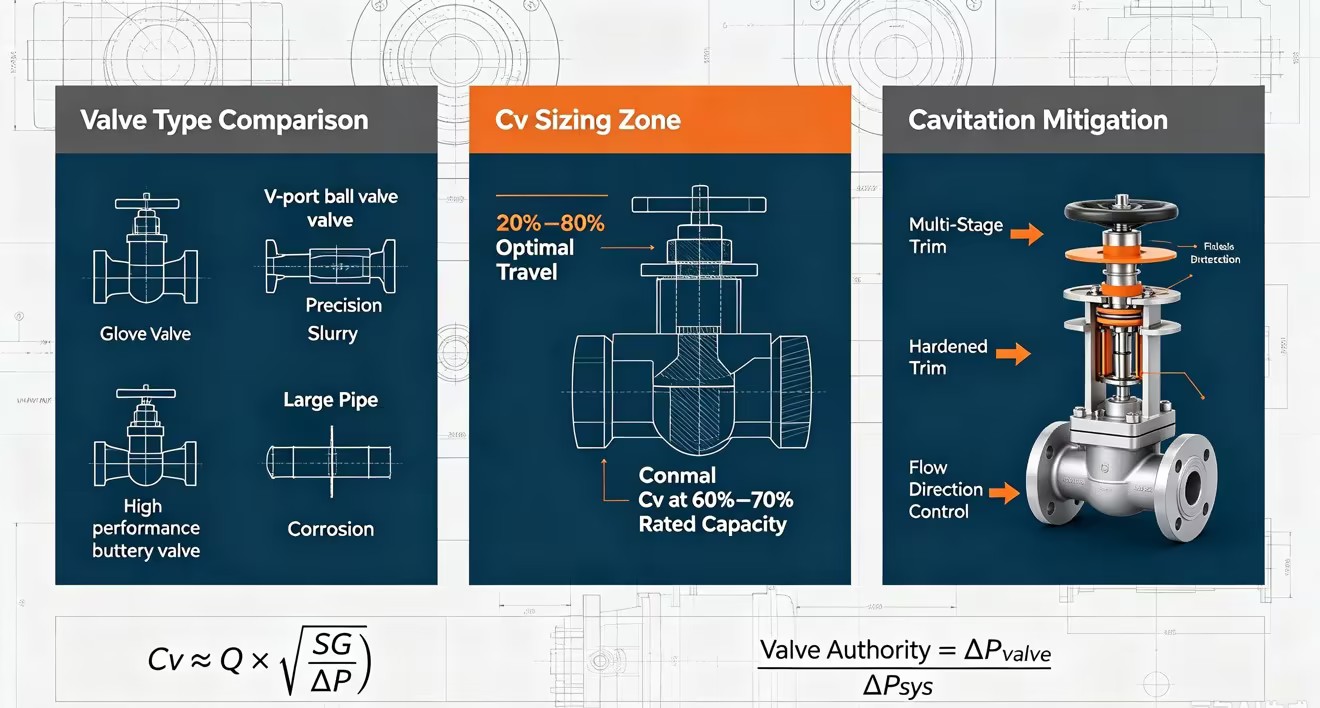
Accurate sizing relies entirely on calculating the Flow Coefficient (Cv). This metric uses your specific flow rate, fluid specific gravity, and allowable pressure drop. It determines the exact volumetric flow capacity required to satisfy the process. Conceptually, one Cv equals one US gallon per minute of water at 60 degrees Fahrenheit flowing through the valve with a one psi pressure drop. Follow a strict engineering rule of thumb during sizing. The equipment should operate between 20% and 80% open during normal flow conditions. This specific range ensures control stability. It keeps the closure element away from the seat to prevent erosion while providing a sufficient buffer for unexpected process surges.
Gather the absolute maximum, normal, and minimum flow rates for the specific process loop.
Determine the allowable pressure drop across the valve at each of those three flow conditions.
Calculate the required Cv for the maximum, normal, and minimum states using standard ISA sizing equations.
Select a valve body and trim size where the normal calculated Cv falls around 60% to 70% of the valve's total rated capacity.
Differential pressure plays a critical role in both sizing and actuator selection. It directly impacts the mechanical forces acting on the internal trim. A valve must take a sufficient percentage of the total system pressure drop to maintain authority over the flow. This concept is known as valve authority. Authority is the ratio of the pressure drop across the fully open valve to the total system pressure drop. If the authority drops below 0.3, the installed flow characteristic distorts severely. An equal percentage valve will start acting like a linear valve. This ruins loop tuning and makes stable control impossible. The system piping will dictate the flow rate rather than the control loop.
Select body and trim materials based strictly on fluid corrosivity, erosion potential, and operating temperature. Common options include WCB carbon steel for general utility use and CF8M stainless steel for moderate corrosion resistance. Exotic alloys like Hastelloy, Monel, or Titanium become necessary for extreme chemical environments. For the internal trim, 316 stainless steel is the industry standard. Add Stellite hardfacing to the plug and seat for high-pressure-drop applications to prevent wire drawing and erosion. You must also align your specification with ANSI/FCI 70-2 seat leakage classes. Match the specific class to your application requirements to avoid over-specifying and inflating project budgets.
| Leakage Class | Maximum Leakage Allowable | Typical Test Medium |
|---|---|---|
| Class II | 0.5% of rated capacity | Air or Water |
| Class III | 0.1% of rated capacity | Air or Water |
| Class IV | 0.01% of rated capacity | Air or Water |
| Class V | 5 x 10^-4 ml/min of water per inch of orifice diameter per psi differential | Water |
| Class VI | Bubbles per minute (varies by port size) | Air or Nitrogen |
Heavy industrial requirements focus heavily on extreme operating parameters. You must account for high temperatures, aggressive corrosivity, and massive differential pressures. The focus is on ruggedness, heavy flanged bodies, and metallurgical integrity. Commercial HVAC and hydronic systems operate under entirely different priorities. They use threaded or grooved connections with bronze or cast iron bodies. They focus on maintaining consistent flow across varying building loads to ensure occupant comfort. Pressure Independent Control Valves (PICVs) offer a specialized modulating solution for these hydronic networks. They combine a differential pressure regulator with a control valve. The internal regulator absorbs system pressure fluctuations, ensuring the chilled or hot water coil receives the exact required flow rate regardless of what other valves in the building are doing.
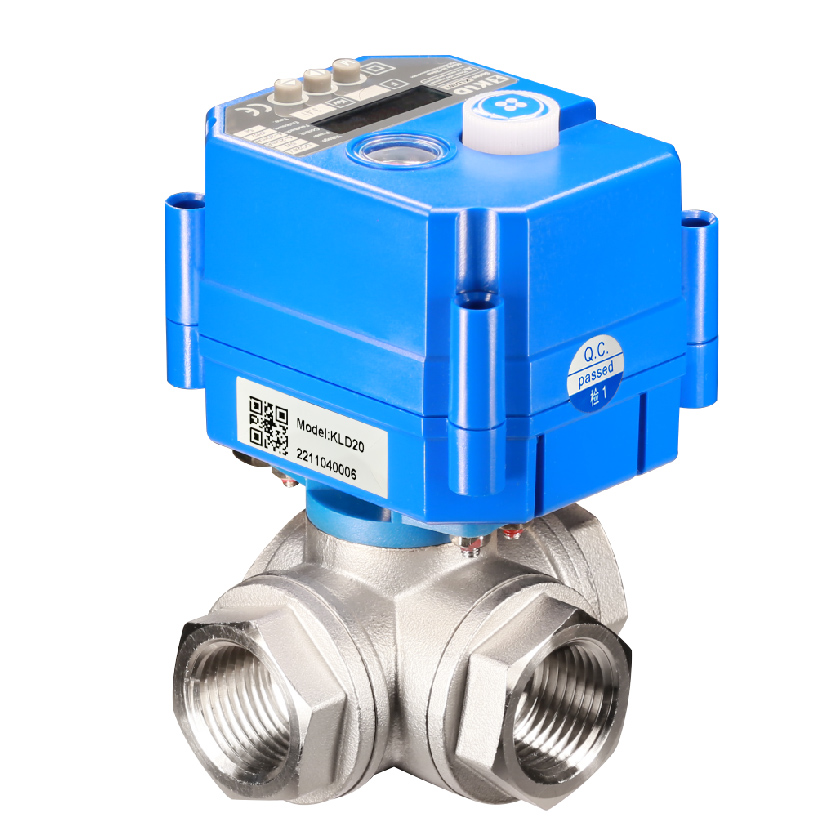
Pneumatic diaphragm actuators are the industry workhorse. They use a simple spring and rubber diaphragm mechanism. They offer proven reliability and provide immediate fail-safe capabilities through heavy-duty spring-return actions. Their speed of response is excellent for fast-moving process loops. Electric actuators use motors and gear trains. They are ideal for remote pipeline applications lacking instrument air infrastructure. Recent advancements have drastically improved their continuous duty-cycle capabilities and positioning precision. Hydraulic and electro-hydraulic actuators handle the most extreme conditions. They utilize a self-contained hydraulic pump driven by an electric motor. They remain the go-to solution for massive torque requirements, high thrust demands, and rapid emergency response times on large pipeline valves.
The physical valve relies entirely on its control loop to function. A positioner measures the actual stem position and adjusts the motive force to the actuator until the stem reaches the target. Digital smart positioners eliminate mechanical stiction and drastically reduce hysteresis. They ensure the closure element exactly matches the incoming control signal from the PLC or DCS. This signal typically utilizes standard 4-20mA wiring or digital protocols like HART and Foundation Fieldbus. Smart positioners use microprocessors to run auto-calibration routines. They also offer advanced onboard diagnostic capabilities. They continuously track total valve travel, cycle counts, friction levels, and breakaway torque. This data feeds directly into predictive maintenance software, allowing technicians to rebuild the equipment before a catastrophic failure occurs.
Cavitation occurs when fluid pressure drops below its vapor pressure at the vena contracta, which is the narrowest point of flow inside the valve body. This pressure drop causes vapor bubbles to form. As the fluid moves into the larger downstream area, velocity decreases and pressure recovers. This recovery forces the bubbles to violently collapse, releasing destructive shockwaves. Flashing happens when the fluid remains a vapor downstream because the pressure never recovers above the vapor pressure limit. Both phenomena rapidly destroy internal metal components through severe pitting. Mitigation requires specific engineering strategies. Use multi-stage anti-cavitation trim to break down the pressure drop gradually across several stages, preventing the pressure from ever dipping below the vapor limit. Employ hardened materials like Stellite overlay for critical wear areas. You can also alter the flow direction to flow over the plug rather than under it, directing the collapsing bubbles into the center of the pipe away from metal surfaces.
High pressure drops in compressible fluids generate severe aerodynamic noise as the gas expands rapidly. This acoustic energy causes destructive high-frequency vibrations that degrade the piping infrastructure, crystallize metal welds, and damage nearby instrumentation. Noise levels above 85 dBA also pose severe safety risks to plant personnel. You must manage this energy safely. Solutions include installing specialized noise-attenuating whisper trims inside the valve body. These trims use cages with thousands of small, laser-cut holes to split the main flow into smaller, quieter streams. You can also use downstream diffusers to manage the gas expansion gradually over a larger area. Specifying thicker pipe schedules helps contain the acoustic energy safely within the piping boundary, preventing it from radiating into the facility.
Oversizing remains the most frequent and damaging engineering error in flow control. When you select a valve based solely on the line size rather than the calculated Cv, the valve ends up far too large for the process. An oversized valve operates at 5% to 10% open to achieve the required flow rate. The plug sits right on the seat. High-velocity fluid shoots through this tiny gap, causing severe wire drawing and erosion of the sealing surfaces. It also results in poor control resolution. Small actuator movements cause massive changes in flow. The control loop will constantly hunt for the correct position, oscillating endlessly. This instability wears out the actuator packing, destroys the positioner linkages, and disrupts the entire process loop. Always size for the actual calculated Cv.
Audit your existing piping system to determine the exact minimum, normal, and maximum flow rates before evaluating any hardware options.
Calculate the required Flow Coefficient (Cv) for all operating conditions to establish your baseline capacity and prevent destructive oversizing.
Select a valve body style that matches your required flow characteristic, pressure drop limits, and physical pipe constraints.
Specify trim materials and leakage classes based strictly on the fluid's corrosivity, temperature, and the system's shutoff requirements.
Install a smart digital positioner to eliminate mechanical hysteresis, ensure precise tracking, and enable predictive maintenance monitoring.
A: A modulating valve continuously adjusts the flow area to control fluid rates precisely. It throttles the flow based on a variable analog or digital signal. An on-off valve only operates in two distinct positions: fully open or fully closed. On-off valves are designed strictly for isolation, not for regulating flow rates.
A: The Cv determines the exact flow capacity a valve can handle at a specific pressure drop. Accurate calculation prevents oversizing. Oversized valves operate too close to the seat, causing rapid wear, poor control resolution, and system instability. Proper Cv sizing ensures the equipment operates in its optimal control range.
A: Standard ball valves are generally unsuitable for precise modulation due to their high recovery and non-linear flow characteristics. However, characterized ball valves, such as V-port designs, are specifically engineered for modulation. They provide a precise flow profile and high rangeability suitable for demanding throttling applications.
A: Cavitation occurs when the fluid pressure drops below its vapor pressure inside the valve, forming bubbles. As pressure recovers downstream, these bubbles violently collapse. This collapse generates localized shockwaves that can severely damage internal trim and piping. Multi-stage trims are used to prevent this phenomenon.
A: Pneumatic actuators are preferred when you need rapid response times, proven reliability, and mechanical fail-safe actions via heavy-duty spring returns. Electric actuators are chosen when instrument air is unavailable, or when precise digital integration is required without installing new pneumatic infrastructure.


