

Views: 0 Author: Site Editor Publish Time: 2026-11-09 Origin: Site


A 4–20mA water flow control valve regulates water flow through an analog control signal. Its performance depends on actuator accuracy, valve characteristics, pressure ratings, and applicable industry standards. Understanding these specifications helps engineers achieve stable, reliable flow control.
Table of Contents
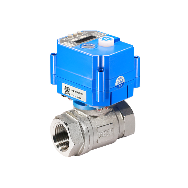
A 4–20mA water flow control valve combines a motorized valve, an electric actuator, and an analog control interface. The actuator receives a signal from a programmable logic controller (PLC), building management system (BMS), or industrial control system.
It then adjusts the valve position to regulate water flow through the pipeline.
Unlike an on/off valve, which operates at two positions, a modulating valve can maintain intermediate positions. This allows the control system to respond to changing flow requirements without repeatedly opening and closing the valve.
The 4–20mA signal represents a defined control range. In a typical direct-acting configuration, the current corresponds to valve travel as follows:
Input Signal | Valve Position | Control Response |
|---|---|---|
4mA | 0% open | Fully closed |
8mA | 25% open | Partially open |
12mA | 50% open | Half travel |
16mA | 75% open | Partially open |
20mA | 100% open | Fully open |
These positions assume a linear relationship between the control signal and actuator travel.
Some actuators also support reverse-acting control. In this configuration, 4mA commands the open position, while 20mA commands the closed position.
The 4mA baseline provides a live zero, helping the controller distinguish the minimum valid signal from a complete loss of current.
A common engineering misconception is that 50% valve opening always produces 50% of the maximum water flow.
In practice, water flow depends on several factors:
Valve flow characteristic
Differential pressure across the valve
Valve flow coefficient (Kv or Cv)
Pipeline resistance
Pump operating conditions
For example, a valve with an equal-percentage characteristic behaves differently from one with a linear characteristic.
Therefore, precise water flow regulation requires more than accurate actuator positioning. The valve must also have a suitable flow characteristic and operate within the intended hydraulic conditions.
Technical specifications determine whether a valve can provide reliable performance under actual operating conditions.
Engineers should evaluate electrical control parameters and mechanical valve characteristics together.

The following parameters are particularly important when integrating a modulating water control valve with an industrial automation system.
Technical Parameter | Description | Engineering Consideration |
|---|---|---|
Control Signal | 4–20mA analog input | Must match the controller output |
Power Supply | Model-dependent AC or DC | Confirm voltage and electrical load |
Position Accuracy | Difference between commanded and actual position | Affects positioning performance |
Control Direction | Direct or reverse acting | Verify before commissioning |
Deadband | Minimum change required to trigger movement | Influences stability and actuator cycling |
Operating Time | Time required for valve travel | Match process response requirements |
Feedback Signal | Position information, if provided | Confirm availability and output format |
Fail-Safe Function | Defined response to a fault or power loss | Verify available actuator configuration |
Position accuracy and flow regulation accuracy should not be treated as identical specifications.
An actuator may position the valve accurately while the actual water flow changes because of variations in differential pressure.
The mechanical design determines the suitability of a valve for a water distribution or industrial process application.
Parameter | Technical Significance |
|---|---|
Nominal Diameter | Determines the nominal valve size |
Pressure Rating | Defines the allowable pressure under specified conditions |
Flow Coefficient | Supports hydraulic sizing calculations |
Valve Body Material | Affects corrosion resistance and application compatibility |
Seal Material | Influences sealing performance and media compatibility |
Flow Characteristic | Determines the relationship between valve travel and flow capacity |
Medium Temperature | Defines the permitted operating temperature range |
Connection Type | Must match pipeline installation requirements |
Enclosure Protection | Protects electrical components against environmental exposure |
Material selection should consider water chemistry, operating temperature, corrosion potential, and any applicable drinking-water requirements.
A valve suitable for an ordinary closed-loop cooling system is not automatically approved for potable water service.
The KLD20T two-way motorized ball valve provides a practical example of a compact 4–20mA modulating valve.
Based on the published product specifications, the model provides the following characteristics:
Specification | KLD20T 2-Way Modulating Ball Valve |
|---|---|
Valve Type | 2-way motorized ball valve |
Nominal Size | DN8–DN32 |
Control Input | 4–20mA and other selectable analog options |
Position Accuracy | ±1% |
Adjustable Deadband | 1%–9.9% |
Maximum Pressure | 1.0 MPa (PN10) |
Medium Temperature | 0°C to 100°C |
Ambient Temperature | −20°C to 45°C |
Enclosure Rating | IP67 |
Operating Time | Approximately 5 seconds |
Flow Characteristics | Linear, approaching equal-percentage, or quick-opening options |
Valve Body Materials | Nickel-plated brass, 304, 316L, and 2507 options |
Power Supply | DC12V, DC24V, and AC220V versions |
The KLD20T also features patented floating-seal technology, an OLED valve-position display, and optional fail-safe functionality. Its compact design is intended for small equipment and small-bore pipeline applications.
Explore the KLD20T 4–20mA Modulating 2-Way Motorized Ball Valve for detailed specifications, dimensions, and available configurations.
The figures above are specific to the KLD20T and should not be interpreted as universal specifications for all 4–20mA water flow control valves.
Industry standards provide a common technical framework for evaluating control signals, valve performance, and mechanical compatibility.
However, no single standard covers every aspect of a 4–20mA water flow control valve.
Different standards address different parts of the assembly.
IEC 60381-1 addresses analog direct-current signals used to transmit information between elements of industrial process measurement and control systems.
It provides an important technical reference for 4–20mA communication.
For valve automation, signal compatibility helps ensure that the actuator can correctly interpret commands from a compatible industrial controller.
Important system-level considerations include current-loop configuration, power supply, wiring resistance, electrical noise, and supported input ranges.
Engineers should verify whether the controller provides an active or passive analog output and whether the actuator input is compatible.
For the official standard description, consult IEC 60381-1: Analogue Signals for Process Control Systems.
The IEC 60534 series covers technical subjects related to industrial process control valves.
Relevant parts include:
Standard | Main Subject |
|---|---|
IEC 60534-1 | Control valve terminology and general considerations |
IEC 60534-2-1 | Flow capacity sizing equations |
IEC 60534-2-3 | Flow capacity test procedures |
IEC 60534-2-4 | Inherent flow characteristics and rangeability |
IEC 60534-4 | Inspection and routine testing |
These documents help engineers understand valve sizing, performance evaluation, and testing requirements.
For water systems, the sizing principles are particularly relevant because valve capacity must be evaluated against flow rate and differential pressure.
The IEC 60534-1:2023 standard preview provides additional information on control valve terminology and general considerations.
A product should not be described as fully compliant with the IEC 60534 series unless the relevant requirements and supporting documentation have been verified.
ISO 5211 specifies attachment requirements for part-turn actuators used with industrial valves.
The standard addresses mounting interface dimensions and related mechanical requirements.
It is relevant when an actuator must be attached to a compatible quarter-turn ball or butterfly valve.
The current ISO 5211:2026 edition supersedes ISO 5211:2023.
Part-turn actuator attachments
For a complete valve assembly, mounting compatibility should be confirmed using actual manufacturer drawings and product specifications.
Electrical actuators may also need to meet requirements relating to enclosure protection, electrical safety, and installation conditions.
IP ratings describe protection against dust and water ingress. For example, IP67 indicates a dust-tight enclosure designed to withstand specified temporary immersion conditions.
However, IP67 does not automatically establish suitability for continuous underwater operation.
Similarly, CE marking, RoHS declarations, and other regulatory documentation address different obligations. Their applicability depends on the product, jurisdiction, and intended use.
Engineers should review the manufacturer's actual declarations and test documentation rather than assuming compliance from the presence of a 4–20mA input.
A modulating valve controls its opening position, but the valve's internal flow characteristic influences how much water passes through it.
Selecting an appropriate characteristic can improve controllability across the intended operating range.
A linear characteristic is designed so that the flow coefficient increases approximately in proportion to valve travel under a constant differential pressure.
This can be useful in applications where relatively predictable flow-capacity changes are required.
However, the installed flow characteristic may differ from the inherent characteristic because the pressure drop across the valve changes as the system operates.
An equal-percentage valve provides a characteristic in which equal increments of valve travel produce approximately equal percentage changes in flow coefficient.
This is useful where the system operates over a wide flow range or experiences significant changes in pressure conditions.
For many process control applications, this characteristic can provide more balanced control across different operating points.
A quick-opening valve provides a relatively large increase in flow capacity during the initial part of its travel.
This behavior may be useful in applications requiring rapid changes toward a high-flow condition.
However, quick-opening characteristics are generally less suitable when fine throttling is required over a broad operating range.
Flow Characteristic | Typical Behavior | Potential Application |
|---|---|---|
Linear | Approximately proportional capacity change | Systems with relatively stable differential pressure |
Equal Percentage | Progressive capacity increase | Variable-load water circulation |
Quick Opening | Large initial capacity increase | Applications emphasizing rapid opening |
The appropriate characteristic should be determined from the installed hydraulic system, not solely from the actuator input signal.
The flow coefficient is one of the most important parameters in valve specification.
For water service, Kv and Cv values describe the relationship between flow capacity and pressure drop.
For water at approximately standard reference conditions, a simplified sizing relationship is:
\[ Q=K_v\sqrt{\Delta P} \]
Where:
\(Q\) = water flow rate in m³/h
\(K_v\) = metric valve flow coefficient
\(\Delta P\) = pressure drop across the valve in bar
This simplified expression assumes water with a relative density near 1 and liquid flow without significant cavitation or flashing.
For other liquids, the density correction must be considered.
Suppose a control valve has a Kv value of 4 and operates at a differential pressure of 0.25 bar.
The estimated water flow is:
\[ Q=4\times\sqrt{0.25} \]
\[ Q=2\ \text{m}^3/\text{h} \]
The estimated flow is 2 m³/h at the specified operating point.
This example illustrates the basic relationship only. Actual valve sizing should account for the installed pressure conditions, minimum and maximum flow requirements, and potential cavitation.
Two valves with the same nominal diameter may have different internal port geometries and flow coefficients.
A larger nominal diameter does not always provide better regulation.
An oversized control valve may operate close to its closed position during normal service. This can reduce the usable control range and make fine adjustments more difficult.
For this reason, engineers should review flow coefficient data alongside nominal diameter and control characteristics.
4–20mA modulating water valves are useful in systems requiring adjustable flow rather than simple isolation.
Their applications depend on operating pressure, water quality, valve materials, and the available control system.
Water treatment equipment may require controlled flow through filtration units, auxiliary water lines, or process distribution circuits.
A modulating valve can adjust the flow according to controller commands.
For example, a PLC may respond to a flowmeter reading by increasing or reducing valve opening.
This feedback arrangement can help maintain a target flow despite changes in system conditions, provided the valve has sufficient control authority.
In cooling water systems, modulating valves help regulate the supply of water to heat exchangers or other thermal equipment.
The controller can adjust valve opening according to temperature, flow, or pressure feedback.
A suitable flow characteristic and appropriately sized valve can improve controllability under changing thermal loads.
Compact valves can also support water control inside automated equipment.
Examples include:
Equipment cooling circuits
Automated water distribution units
Process machinery
Temperature-control equipment
Industrial water-saving systems
For applications requiring additional actuator functions or remote control capabilities, explore KLD's Smart Modulating Electric Actuators.
Correct installation and commissioning are essential for consistent valve operation.
Electrical compatibility alone does not guarantee stable water flow control.
Before energizing the actuator, confirm the supply voltage and analog input requirements.
Check the controller output type, wiring polarity, current-loop configuration, and applicable grounding instructions.
Signal wiring should be routed according to the manufacturer's recommendations and the site's electrical installation practices.
The actuator's control direction must agree with the process control strategy.
For direct-acting control, increasing current may move the valve toward the fully open position.
For reverse-acting control, increasing current may move the valve toward the closed position.
Testing the 4mA, 12mA, and 20mA command points helps confirm the configured direction and travel response.
Fail-safe functionality must be evaluated separately from ordinary positioning control.
A loss of the 4–20mA signal does not necessarily produce the same response as a loss of electrical power.
Depending on the actuator configuration, the valve may hold its position, move to a predetermined position, or follow another configured action.
The KLD20T series offers optional fail-safe configurations. The required behavior should be confirmed for the ordered version.
Final commissioning should include tests under representative operating conditions.
Compare the controller's requested flow with the measured flow and check the stability of the response.
If the valve repeatedly moves back and forth, review controller tuning, actuator deadband, feedback quality, and hydraulic system behavior.
The objective is stable process control without unnecessary actuator movement.
It is a motorized valve that receives analog current commands to adjust valve position and regulate water flow.
No. It may represent 50% valve travel, but actual flow depends on the valve characteristic and pressure conditions.
IEC 60381-1 covers analog current signals, while IEC 60534 addresses industrial control valve performance topics.
Yes, if the PLC analog output and actuator input are electrically compatible and correctly configured.
IP67 may suit certain environments, but chemical exposure, immersion conditions, and installation requirements must also be considered.
A 4–20mA water flow control valve combines analog positioning with mechanical flow regulation. Reliable performance requires suitable hydraulic sizing, accurate control, compatible materials, and appropriate technical standards.
KLD offers compact modulating valve solutions for industrial equipment and automated fluid control applications. Its product range supports different valve configurations, flow characteristics, and control requirements.
For a specific project, provide the required flow range, pressure conditions, water temperature, and control interface so the appropriate valve configuration can be evaluated.


